テスラコイルの作り方 (jp)
テスラコイルのコイル部分の設計方法について, 独自の研究(笑)や調査によって色々分かったのでまとめて紹介します。なお, ココに書いてある方法はあくまで「我流」ですのでそのつもりで^^;
まずは適当に原理の解説をしますので, 手順だけ知りたければすっ飛ばしても問題は無いでしょう。
テスラコイルにおける最高のコイル
テスラコイルにおいて, コイルを適当に巻いてしまっては最大のパフォーマンスを得られない事は明白です。ここでいうパフォーマンスとは, 2次回路が完全に共振した場合にトロイド電圧がどれだけ高くできるか, という事とします。同じ共振周波数の2次回路でも, コイルの径や長さ, 容量球の静電容量の組み合わせは無限に存在しますが, その中でも特に放電長を実現できる組み合わせの点を見つけようというものです。最高のコイルを製作すれば, あとは共振周波数をチューニングする作業に集中する事ができ, 最適な共振点を見つけさえすればテスラコイルへの入力電圧に対して最長の放電を得る事が出来ます。テスラコイルは構造だけ見れば簡単に見えますが, 詳しく検証するとなかなか奥が深い代物であります。テスラコイルにおいて2次コイルの電圧を決定する事項はいくつかありますので, それぞれを順に解説していきます。
テスラコイルの構造
テスラコイルの構造は以下のようになっています。

比較的太い電気伝導性の良いワイヤを数回巻いた1次コイルの中に, 細いワイヤを多く巻いた2次コイルが入っている構造をしています。さらに, 2次コイルの下端(1次コイルに近い方)は大地に良質にアースされ, 逆に上方は容量球(トロイド)が接続されます。これは, 実際には放電電極として機能することになります。以下に, 構造だけに注目したテスラコイルの回路図を示します。

構造はこのようにとても簡単ですが, コレをインピーダンスや磁気結合, 寄生容量など電気基礎を諸々考えたマジメな回路(等価回路)で書くと以下のようになります。
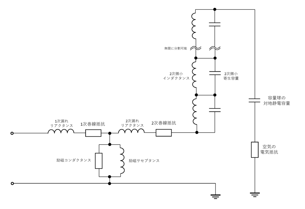
このように多少複雑です。最高のコイルを巻く為に, このような等価回路の回路方程式を計算すれば最適な諸量(インダクタンス, 静電容量等)が算出できますが, とても複雑なうえ, 電気以外の物理事象を全く考慮していないため完璧な結果にはならないでしょう。
とまぁ, テスラコイルの構造はこんなところで。
テスラコイルの放電長を伸ばすには
せっかくテスラコイルを作るのですから, 放電の長さはできるだけ長くしたいところでしょう。では, テスラコイルにおける放電長をかせぐにはどうすれば良いのか考えます。放電長は電圧の高さによって決まると言っても間違いではありませんが, 放電の様子は環境によって大きく左右される現象です。例えば, 気圧, 温度, 気体の種類, 磁場や電場, 電圧波形など, 多くの物理特性によって大きくその形や長さが変わります。しかし, 標準の場合で説明するためここでは環境は空気で1気圧として話を進める事とします。
ということで, とにかく電圧を高くすれば放電長が長くなる, という単純な思考で今後は考えます。2次コイルの電圧を高くする方法として, 以下が考えられます。
・1次回路に印加する電圧を高くする
・1次コイルに流れる電流を大きくする
・2次回路の共振をより正確に調整する
・1次回路, 2次回路のQ値をより大きくする
・2次回路の電圧波形の波長を適当になるよう2次コイルを巻く
・結合係数kを適切に調節する
・無駄な放電をしないような構造にする
○1次回路に印加する電圧を高くする
これは, 変圧器の原理を考えれば分かる事です。1次回路の電圧が高ければ, 自ずと2次側の電圧も比例して高くなります。しかし, 現実的には電源の容量, SGTCの場合はコンデンサの耐圧, SSTC の場合は半導体素子の耐圧&耐流などで制限がかかる事でしょう。

2次コイルの1次コイル近傍は単純な空芯変圧器として見る事ができます。そのため, 1次コイル近傍の2次コイルの巻き数によって, 2次側に誘導される電圧が変化する事になります。この電圧の値は, 2次回路の最終的な出力電圧にとっては重要なファクターです。
○1次コイルに流れる電流を大きくする
これを達成するために考えられたのがDRSSTCです。1次回路にも共振コンデンサを接続し, 共振させることで1次コイルに大きな電流を流します。その結果, 磁束密度がより高くなり, 2次コイルに誘導される電圧も高くなります。

1次コイルだけの場合, 1次コイルに流れる電流は交流なのでコイルのリアクタンス成分と巻線抵抗により1次コイルに流れる電流は制限されます。しかし, 1次コイルに直列にコンデンサを接続し, この回路を共振周波数で駆動すると1次回路におけるリアクタンス成分は消滅するのと等価になり, よって1次コイルに流れる電流を制限するのは1次コイルの巻線抵抗のみとなります。1次コイルは大抵太く頑丈なワイヤで構成され, 巻き数もそれほど多くないので, おおむね抵抗値は0.5[Ω]以下になると思われますので, 駆動電圧によっては瞬間的に数千[A]ほどの電流を流す事ができます。
○2次回路の共振をより正確に調整する
正確に共振している程, 2次回路のインピーダンスが最小になり, 容量球-大地間の電圧が最大になります。
○1次回路, 2次回路のQ値をより大きくする
Q値 (Q factor) は, 共振回路の質を示す値です。RLC直列共振回路では, インダクタンスが大きく, 静電容量と抵抗が小さいほどQ値は大きくなります。つまり, 「できるだけ太いワイヤで, できるだけ径を大きく多く巻く」ことでQ値は大きくする事ができます。1次回路のQ値が高いと, 共振時により大きな電流がコイルを流れ, 2次側により高い電圧が誘導されます。また, 2次回路のQ値が高いと2次回路両端の電圧は高くなります。LC直列共振回路において, コンデンサCの両端には理論上では入力電圧のQ倍の電圧が現れる事になります。
○2次回路の電圧波形の波長を適当になるよう2次コイルを巻く
電圧が進行する速度は, 銅線内ではほぼ光速であるとされています。2次コイルには高周波交流が流れるので, 容量球の先端が電圧波形における最大部分になるように調整すれば, 容量球部分に現れる電圧は大きくなります。これは電波の発射等で使われるアンテナと同じようなもので, 2次回路の導体長を2次電圧波形の1/4波長となるように2次コイルおよび容量球を設計します。大地アースされてる点で, テスラコイルの2次回路はモノポールアンテナのような物といえます。

上図のように2次コイルをほどいたとした場合, ワイヤ長+容量球までの導体長+アース導体長から決まる2次回路長が駆動周波数の1/4波長の場合とそうでない場合とでは, 容量球部の対地電圧が変わってくるのが分かると思います。つまり, 2次コイルの設計で重要なのは, 共振周波数の波長とワイヤ長を可能な限り一致させる事です。
○結合係数kを適切に調節する
2次側が共振するにあたり, 電圧の自由振動を妨げるほど1次コイルと2次コイルの結合を強くしすぎてはいけません。まぁ, 大抵のテスラコイルは空芯コイルとなるはずなので, せいぜい高くて k = 0.1~0.3 ほどでしょう。私の実験によれば, 結合係数は k = 0.25程がベストでした。結合係数は, コイルの形状と2コイル間の距離, 環境の透磁率によって決まる係数です。
○無駄な放電をしないような構造にする
容量球以外の箇所で起こる放電は完全に無駄な物で損失になります。これを防ぐには, コイルの構造をしっかりと考えなければなりません。例えば, 1次コイルと2次コイルの間で放電しないように十分な距離をとったり, 1次コイルをフラットコイルにする, などです。
最高のコイルの設計方法
以上の事項を踏まえてコイルを設計すれば, それは最高のコイルといえるでしょう。しかし, これらの条件を全てバランス良く満たしたコイルを設計するのはそう簡単ではありません。それでは, 実際にどのように2次コイルを設計すれば良いのかを解説します。
「テスラコイルの放電を伸ばすには」に示した条件から, 共振周波数, インダクタンス, 電圧の伝播速度やワイヤの静電容量, Q値の計算式等から諸量の関係式を求め, また実験で得られた結果や既存の論文から得られたデータを用いて関係を具体化した結果, 以下の式が導かれました。「Kamomesanの公式」とでも呼びましょうかね(笑)

N は2次コイルの巻き数です。この式がすばらしいのは, テスラコイルを作るにあたって, 使用するマグネットワイヤの直径 w, 容量球の容量 C が分かるだけで, 上記「テスラコイルの放電長を伸ばすには」で説明した条件のほとんどをクリアしたコイルが巻けるという事にあります。さらに, ワイヤ径と容量球容量は自分の好みで簡単に設定できる値ですね。kamomesanの公式で求められた回数だけ2次コイルを巻けば良いので, あとは測定により共振周波数をもとめ, その共振周波数にあわせた1次回路を作成するだけです。kamomesanの公式では, 最適な容量球の静電容量と巻き数の関係が分かりますので, その関係をできるだけQ値が高くなるようにフィルタリングする事で, 最高のコイルを設計できます。RLC直列共振回路のQ値は次式で算出できます。

ここで, 巻線抵抗 R は銅の抵抗率と巻き数から, 次式で求められます。

インダクタンス L を計算するにあたり長岡係数 A が必要になりますが, 長岡係数の計算は非常に複雑なので, 以下に示すコイルの径長比 a と独自に算出した長岡係数の近似式を用いて計算します。


算出された巻線抵抗 R, インダクタンス L と, 容量球の静電容量 C を Q値の式に代入する事でQ値が計算できます。kamomesanの公式とQ値の算出式を用いることで, 以下のグラフのように容量球の静電容量を変数とした時の共振周波数, Q値, 巻き数 の関係を計算する事が出来ます。

ワイヤ径は0.3[mm]のものを, VU65 (塩ビパイプ) に巻いた時の諸量の関係です。実際に製作できる1次回路の周波数にはスイッチング素子等の応答速度により限界があります。ここで, 仮に製作できる1次回路の最高発振周波数を500[kHz]とすると, 上グラフより, 巻き数はおよそ 626 [回], 容量球の容量は 10 [pF], Q値は 894 であると求める事ができます。この値どおりに2次コイルを巻いた時, そのコイルは「テスラコイルの放電を伸ばすには」に示した条件を満たした物とするとができます。グラフを見れば分かりますが, 1次回路で発振できる周波数が高ければ高いほど, また1次回路の電圧が高ければ高いほど, チューニングはシビアになりますがQ値が大きくなるので大きな放電を期待できることになります。
2次コイルが設計できたら次に1次コイルです。上で作成した2次回路の下部に適当な1次コイルモドキを巻き, 小信号の矩形波を入力する事で, オシロスコープを使用して2次回路の共振周波数を測定します。下図のように装置をセッティングし, 周波数可変の小信号矩形波源(正弦波でも可)の周波数を調整して, オシロスコープに表示される波形の振幅が最大になる周波数(共振周波数)を見つけます。この時注意すべきなのが, 測定の誤差になるので容量球に手などを近づけすぎないという事と, プローブを容量球に近づけすぎない事です。スパークがプローブに当たると最悪オシロスコープが壊れてしまいます^^; 容量球とプローブの距離で波形が大分変化するので, プローブは何らかの方法で固定するのが楽でしょう。

オシロスコープが無い場合は, LCRメータで直接インダクタンスを測定して共振周波数を推測する方法もありますが, この場合では容量球の静電容量の測定が難しく, うまく共振周波数を求められないでしょう。テスラコイルをやるならオシロスコープは1台くらい持っておいた方が良いと思います。今後の電子工作でも必ず使うときが来ますので^^
後は簡単で, 測定した2次側共振周波数で共振するような1次回路を設計するだけです。このときの注意は,
○ 1次コイルに使うワイヤは出来るだけ太く, 銅などの電気伝導性の良い素材を使う。
○ できるだけコイルの巻き数を多くする。
○ 1次-2次コイル間での放電を防ぐため, 2次コイルとはある程度離す。1次コイルと2次コイルの間にどれだけ電位差が出来る(放電しやすい)かは, アース線の長さや1次コイルの形状によって左右されるので, テスラコイルの規模にもよりますが最低でも10mmは離した方が良いかも知れません。
○ 逆コーン状のコイルはお勧めしません。電磁気的にはあの形状にするメリットは得に無いです。
くらいでしょうか。とにかく, 1次コイルが燃えないように, また2次コイル間とで放電しないようにすれば問題無いでしょう。
最終的なテスラコイルの設計手順
導かれた関係式を用いる事で簡単にテスラコイルに最適な2次コイルを設計する事が出来ます。手順は大体以下のようになるでしょう。
① 作りたいテスラコイルのサイズを大まかに決める。
② 2次コイルを巻く空芯筒(塩ビパイプ等)の直径を決める。
③ テスラコイルのサイズを気にして, 2次コイルに使うマグネットワイヤーの径 w を決定する。(後の検証でコイル径に対する理想的なワイヤ径が分かったりします。)
④ 外部のサイトを利用するなどして, 容量球のサイズと大体の静電容量 C を決定する。
⑤ kamomesanの公式に決定した値 w, C を代入して2次コイルの巻き数 N を得る。

⑥ 決めたサイズの容量球を作れる分の材料, 2次コイル用のマグネットワイヤーを購入する。
⑦ 2次コイルを決めた巻き数だけ巻き, 容量球も設計通りに製作する。
⑧ 2次コイルと容量球を合体し, 適当な1次コイルを巻いて共振周波数を測定する。
⑨ 測定した2次コイルの共振周波数と共振するように, かつ燃えないように, 2次コイル間でスパークしないよう気を付けて1次回路を組む。
⑩ 容量球を納得いくまで微調節する。
⑪ やったぜ。
kamomesanの公式を簡単に計算できるExcelシートを用意したので, よければ使ってください。↓
TeslaCoil_calclation_form.xlsx - Google ドライブ
kamomesanの公式の検証
導かれたkamomesanの公式を用いて, 実際にいくつか事例を設定し, 最適なコイルはどのような物になるのかを計算してみたいと思います。
○ [問1] 最高周波数 500 [kHz] の1次フルブリッジ回路を設計できるA氏がいる。手元にVU250のパイプとφ0.4[mm]のUEWがあるとし, 放電長が最大になる為にはA氏は2次コイルを何回巻けば良いか, およびトロイドの容量はいくつにすれば良いかを求めよ。
ここで, UV250は直径が 267[mm], マグネットワイヤの直径が 0.4[mm] と分かっているので, コイル径 D は 267.4[mm], ワイヤ径 w は 0.4[mm] となります。これらの値をkamomesanの公式に代入し, さらにQ値を計算すると以下のグラフに表す特性が求められます。

このグラフから, A氏が作る1次回路の 500 [kHz] で最長の放電を得るためには, 2次コイルの巻き数は 1400 [回], トロイドの静電容量は 30 [pF] と求まります。ちなみに, Q値は 523 です。よって, A氏が作るべき2次コイルは以下のようになるでしょう。
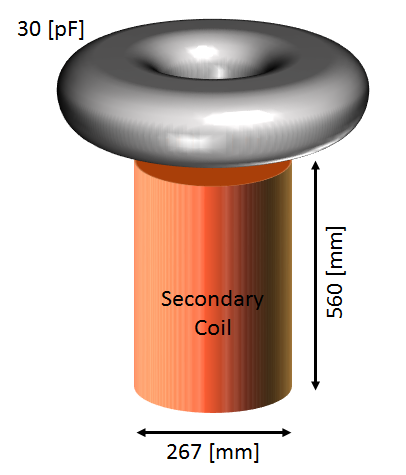
実際には, コイルが短いことにより放電が下に接触してしまうと思われるので, ここから構造的に放電長を伸ばす工夫をする事になると思います。トロイドを高い位置に持っていったり, コイルを巻くパイプ内に絶縁物を詰め込んだり, 設置抵抗を小さくしたり, こだわるならマグネットワイヤーを太いものに変えて巻きなおすのも良いでしょう^^。
○ [問2] 手元にVU65にφ0.1[mm]のUEWを1500[回]巻いた2次コイルを持っているB氏がいる。放電長が最大になる為には, B氏は何pFのトロイドを用意し, 1次回路の発振周波数を何[kHz]にすれば良いかを求めよ。
VU65 の直径は 76[mm]で, マグネットワイヤーの直径が 0.1[mm] と分かっているので, コイル径 D = 76.1[mm], w = 0.1[mm] です。これをkamomesanの公式に代入し, それによって得られた関係からQ値を計算すると以下のグラフに示すような特性が得られます。

このグラフから, 放電を最長にするのに必要なトロイドの静電容量は 16 [pF], この時の共振周波数は 202.6 [kHz] であると求められます。ちなみにQ値は 256 です。
○ [問3] 最高周波数 600 [kHz] の1次フルブリッジ回路を設計できるC氏がいる。手元にVU600のパイプとφ0.6[mm]のUEWがあるとし, 放電長が最大になる為にはC氏は2次コイルを何回巻けば良いか, およびトロイドの容量はいくつにすれば良いか, 1次回路の発振周波数は何kHzにすれば良いかを求めよ。
ここで, UV600は直径が 632[mm], マグネットワイヤの直径が 0.6[mm] と分かっているので, コイル径 D は 632.6[mm], ワイヤ径 w は 0.6[mm] となります。これらの値をkamomesanの公式に代入し, さらにQ値を計算すると以下のグラフに表す特性が求められます。

このグラフから, 最長の放電を得るためには, 2次コイルの巻き数は 252 [回], トロイドの静電容量は 8 [pF] , 1次回路の発振周波数は 252 [kHz] と求まります。ちなみに, Q値は 2660 です。このコイルでは, 巻き数とワイヤ径から分かるように高さが 151 [mm] と, 太く短いコイルになっていることが分かります。この形状は, 放電長を稼ぐのには不向きですので, 実際には多少Q値をあきらめてワイヤ径をさらに大きい物で巻きなおす事や, トロイドを大きなものにする改善が必要となるでしょう。大きいコイルで迫力を求めるほど, 大きなトロイドと太い巻線が必要な事がわかります。
実際に実験してみる
準備中
How to design Tesla coil (en)
About the design method of the coil part of Tesla coil, since various things were found by our own research (lol) and survey, we introduce it collectively. In addition, the method written in here is "my way".
First of all I will explain the principle appropriately. If you only want to know the procedure, you do not have to read it.
The best coil for Tesla coil
In Tesla coil, it is obvious that maximizing performance can not be obtained by sloppily winding the coil. "The performance" mentioned here is how much the topload voltage can be raised when the secondary circuit completely resonates. Even in the secondary circuit of the same resonance frequency, there are infinitely many combinations of the coil diameter, length, and capacitance of the Topload, but in particular it is about finding combinations that can achieve the spark length. If you make the best coil, you can concentrate on the task of tuning the resonance frequency and you can get the longest spark against the input voltage to the Tesla coil as long as you find the optimum resonance point. Tesla coils look easy if you look at only the structure, but it is quite a deep thing if you examine it in detail. Since there are several matters to determine the voltage of the secondary coil in the Tesla coil, we will explain each in turn.
Structure of Tesla coil
The structure of Tesla coil is as follows.
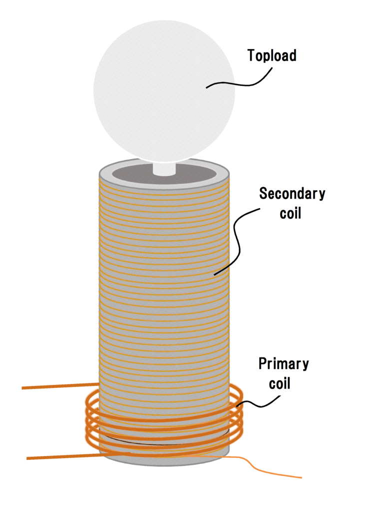
It has a structure that contains a secondary coil with a lot of thin wire wound in a primary coil wound several times with a wire with relatively good electrical conductivity. In addition, the lower end of the secondary coil (the portion close to the primary coil) is grounded to the ground in good quality, and conversely the capacity ball (Topload) is connected on the upper side. In fact, Topload will function as a spark electrode. The schematic of the Tesla coil focusing only on the structure is shown below.

The structure is very simple like this, but if you write it with a detailed circuit (equivalent circuit) which considered electricity as impedance, magnetic coupling, parasitic capacitance etc. various kinds of basic foundation, it becomes as follows.

It is somewhat complicated like this. In order to wind the best coil, calculating the circuit equations of such an equivalent circuit can calculate optimal quantities (inductance, capacitance, etc.), but it is very complicated and not considering various physical phenomena at all It will not be a perfect result.
Okay, the explanation of the structure of Tesla coil is over with this.
How to extend the spark length of Tesla coil
Since it is making a Tesla coil, it is probably where you want to make the length of the spark as long as possible. Let's think about how to earn the spark length in the Tesla coil. Although it is not a mistake to say that the spark length is determined by the voltage, the state of the spark is a phenomenon largely dependent on the environment. For example, its shape and length greatly vary depending on many physical properties such as atmospheric pressure, temperature, kind of gas, magnetic field, electric field, voltage waveform, etc. However, since it is explained in the case of the standard case, here the environment is assumed to be 1 atm of standard air.
So I think in the future with a simple thinking that if the voltage is raised anyway the spark length will be long. As a method of increasing the voltage of the secondary coil, the following can be considered.
・ Increase the voltage applied to the primary circuit
・ Increase the current of the primary coil
・ Adjust the resonance of the secondary circuit more accurately
・ Increase the Q factor of the primary circuit and the secondary circuit
・ The secondary coil is wound so that the wavelength of the voltage waveform of the secondary circuit becomes appropriate
・ Adjust the coupling coefficient k appropriately
・ Make a structure that does not wastefully sparks
○Increase the voltage applied to the primary circuit
This is understandable given the principle of the transformer. If the voltage of the primary circuit is high, the voltage of the secondary side naturally increases proportionally. However, in reality it will be limited by the capacity of the power supply, the withstand voltage of the capacitor in the case of SGTC, and withstand voltage & permissible current of the semiconductor element in the case of SSTC.

The vicinity of the primary coil of the secondary coil can be seen as a simple air core transformer. Therefore, depending on the number of turns of the secondary coil near the primary coil, the voltage induced to the secondary side changes. The value of this voltage is an important factor for the final output voltage of the secondary circuit.
○Increase the current of the primary coil
DRSSTC was thought to accomplish this. A resonance capacitor is connected also to the primary circuit, and by making it resonate, a large current flows in the primary coil. As a result, the magnetic flux density becomes higher and the voltage induced in the secondary coil also increases.

In the case of only the primary coil, the current flowing through the primary coil is limited, so the current flowing through the primary coil is limited by the reactance component of the coil and the winding resistance. However, if a capacitor is connected in series to the primary coil and this circuit is driven at the resonance frequency, the reactance component in the primary circuit will be equivalent to eliminating the reactance component in the primary circuit, It becomes only winding resistance. Since the primary coil is usually composed of a thick and sturdy wire and the number of turns is not so much, it is likely that the resistance value will be less than 0.5 [Ω], so depending on the drive voltage it will instantaneously be about several thousand [A] Current can flow.
○Adjust the resonance of the secondary circuit more accurately
The more accurately resonating, the smaller the impedance of the secondary circuit becomes, and the voltage between the Topload and the ground becomes maximum.
○Increase the Q factor of the primary circuit and the secondary circuit
The Q factor is a value indicating the quality of the resonance circuit. In the RLC series resonant circuit, the larger the inductance, the smaller the capacitance and resistance, the higher the Q factor. In other words, the Q factor can be increased by "wring the wire as much as possible with as much wire as possible and winding as much as possible." When the Q factor of the primary circuit is high, a larger current flows through the coil during resonance and a higher voltage is induced on the secondary side. Also, if the Q factor of the secondary circuit is high, the voltage across the secondary circuit will be high. In the LC series resonant circuit, a voltage Q times the input voltage appears theoretically at both ends of the capacitor C. (C is Topload in the case of Tesla coil)
○The secondary coil is wound so that the wavelength of the voltage waveform of the secondary circuit becomes appropriate
The speed of voltage is said to be nearly light speed in copper wire. Since high frequency alternating current flows in the secondary coil, if the tip of the Topload is adjusted so that it becomes the maximum part of the voltage waveform, the voltage appearing in the Topload part increases. This is the same as the antenna used for radio wave emission etc, and design the secondary coil and the Topload so that the conductor length of the secondary circuit becomes quarter wavelength of the secondary voltage waveform. In the point that the lower part is grounded, the Tesla coil's secondary circuit is like a monopole antenna.
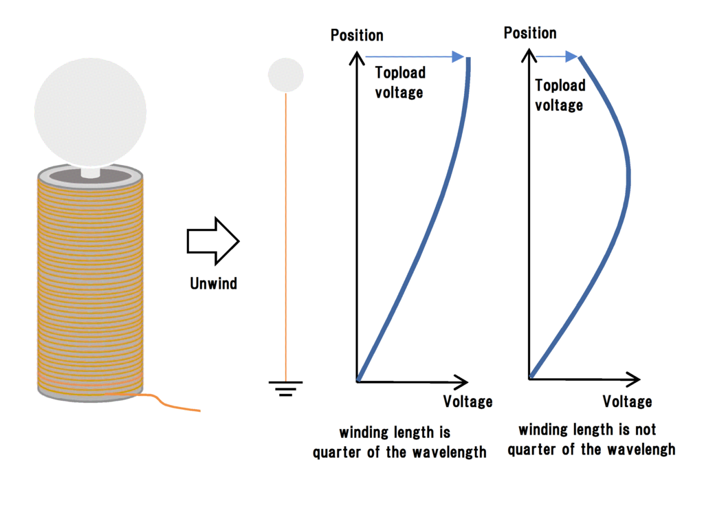
In the case where the secondary coil is unwound as shown in the above figure, in the case where the secondary circuit length determined from the wire length + the conductor length up to the Topload + the earth conductor length is quarter wavelength of the driving frequency and the case where it is not , I think you can see that the ground voltage of the Topload part changes. In other words, it is important to match the wavelength of the resonance frequency with the wire length as much as possible in designing the secondary coil.
○Adjust the coupling coefficient k appropriately
In order for the secondary side to resonate, the coupling between the primary coil and the secondary coil should not be too strong so as to prevent free oscillation of the voltage. Well, most Tesla coils are supposed to be air core coils, so it will be at most as high as k = 0.1 to 0.3. According to my experiment, the coupling coefficient was the best for k = 0.25. The coupling coefficient is a coefficient determined by the coil shape, the distance between two coils, and the magnetic permeability of the environment.
○Make a structure that does not wastefully sparks
Spark occurring in places other than the Topload is completely wasted and losses. To prevent this, you must consider the structure of the coil firmly. For example, take a sufficient distance not to spark between the primary coil and the secondary coil, or make the primary coil flat coil.
How to design the best coil
If coils are designed based on the above matters, it can be said that it is the best coil. However, it is not so easy to design a coil that satisfies all these conditions in a well-balanced manner. Then, let's explain how to actually design the secondary coil.
From the condition shown in "How to extend the spark length of Tesla coil", various relational expressions are obtained from the resonance frequency, the inductance, the propagation speed of the voltage, the capacitance of the wire, the calculation formula of the Q factor, etc., As a result of concretizing relations using data obtained from the results and existing papers, the following formula was derived. Shall I call it "Kamomesan's formula" (lol)

N is the number of turns of the secondary coil. The formula is wonderful. In making a Tesla coil, just by knowing the diameter w of the magnet wire to be used and the capacity C of the topload, the coil that almost cleared the conditions described in "How to extend the spark length of Tesla coil" It is possible to wind it. In addition, wire diameter and topload capacity are values that can be easily set by your preference. Since we only need to wind the secondary coil as many times as required by kamomesan's formula, we only determine the resonance frequency by measurement and create a primary circuit that matches the resonance frequency. In kamomesan's formula, the relationship between the capacitance of the optimum topload and the number of turns can be found, so by filtering the relation as high as possible for the Q factor, the best coil can be designed. The Q factor of the RLC series resonance circuit can be calculated by the following equation.

Here, winding resistance R can be obtained from the following equation from the resistivity of copper and the number of turns.

Nagaoka coefficient A is necessary to calculate inductance L, but since the calculation of Nagaoka coefficient is very complicated, it is calculated by using the approximate expression of the coil diameter length ratio 'a' and the Nagaoka coefficient independently calculated.


The Q factor can be calculated by substituting the calculated winding resistance R, inductance L and the capacitance C of the topload into the expression of the Q factor. By using kamomesan's formulas and Q factor calculation formulas, we can calculate the relationship between the resonance frequency, Q factor, and number of turns when the capacitance of the topload is used as a variable as shown in the graph below.

It is a relationship of various values when wire diameter is 0.3 [mm] when wound on VU 65 (PVC pipe). The frequency of the primary circuit that can actually be fabricated is limited by the response speed of switching semiconductors and others. Here, assuming that the maximum oscillation frequency of the primary circuit that can be manufactured is 500 kHz, the number of turns is about 626 turns, the capacity of the topload is 10 pF, and the Q factor is 894 from the upper graph And you can ask. When winding the secondary coil according to this value, the coil can be made to satisfy the condition shown in "How to extend the spark length of Tesla coil". As you can see from the graph, the higher the frequency that can be oscillated in the primary circuit and the higher the voltage of the primary circuit, the more severe the tuning will be but the larger the Q factor will be, the greater the spark expected You will be able to do.
Once the secondary coil can be designed, next is the primary coil. By winding an appropriate primary coil coil at the bottom of the secondary circuit created above and inputting a small signal rectangular wave, measure the resonance frequency of the secondary circuit using an oscilloscope. Set the equipment as shown below and find the frequency (resonance frequency) at which the amplitude of the waveform displayed on the oscilloscope is maximized by adjusting the frequency of a frequency-adjustable small-signal rectangular wave source (it can be a sine wave). The thing to watch out at this time is that it is an error in measurement, so not to bring your hands close to the topload and not to bring the probe closer to the topload. The worst the oscilloscope breaks when the spark strikes the probe :( Because the waveform changes largely at the distance between the topload and the probes should be fixed somewhere.
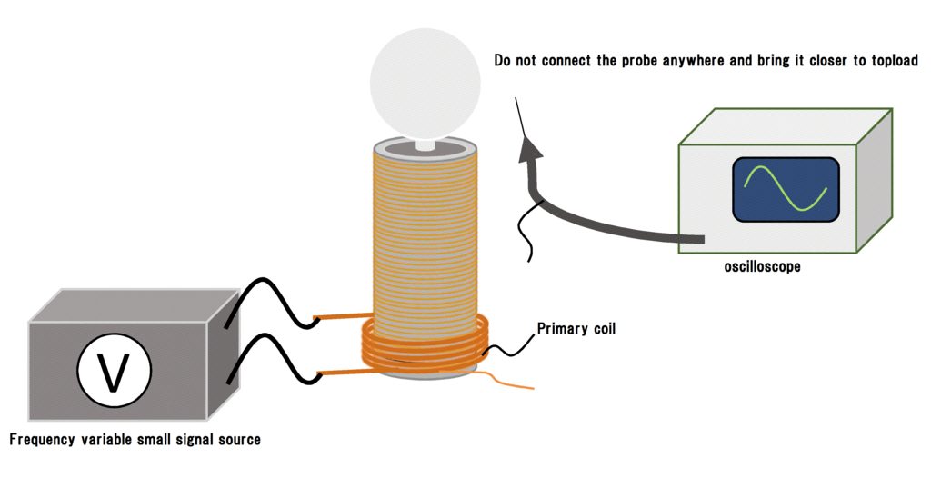
In the absence of an oscilloscope, there is also a method of estimating the resonance frequency directly by measuring the inductance with the LCR meter, but in this case it is difficult to measure the capacitance of the topload and the resonance frequency can not be obtained successfully. If you do Tesla coil, I think that it is better to own about 1 oscilloscope. Since it will certainly come to be used even in future electronic work :)
After that it is easy to design a primary circuit that resonates at the measured secondary side resonance frequency. In this case,
○ The wire used for the primary coil is as thick as possible and uses a material with good electrical conductivity such as copper.
○ Increase the winding turn of the coil as much as possible.
○ To prevent spark between primary and secondary coils, separate the secondary coils to some extent. How much potential difference can be made between the primary and secondary coils (this is the cause of the spark) depends on the length of the ground wire and the shape of the primary coil, so depending on the size of the Tesla coil It may be better to separate at least 10 mm.
○ Inverse cone shaped coils are not recommended. Electromagnetically there is no advantage to make that shape.
Anyway, if you do not let the primary coil burn and spark between the secondary coils, it will not have any problem.
Final Tesla coil design procedure
By using the led kamomesan's formulas it is easy to design a secondary coil optimal for Tesla coil. The procedure will be roughly as follows.
① Roughly decide the size of the Tesla coil you want to make.
② Determine the diameter of an air core barrel (such as PVC pipe) around which the secondary coil is wound.
③ Worry about the size of the Tesla coil and determine the diameter w of the magnet wire used for the secondary coil. (I will know the ideal wire diameter for the coil diameter in later verification.)
④ Determine the size of the topload and the approximate electrostatic capacity C by using an external site.
⑤ Assign the determined values w and C to kamomesan's fomula to obtain the number of turns N of the secondary coil.

⑥ Purchase the material that can produce the capacity bulb of the determined size and the magnet wire for the secondary coil.
⑦ Wind the secondary coil by the determined number of turns, and make topload as designed.
⑧ Combine the secondary coil and the topload, wind the suitable primary coil, and measure the resonance frequency.
⑨ Make sure not to spark between the secondary coils so as to resonate with the resonance frequency of the measured secondary coil and not to burn, and form a primary circuit.
⑩ Adjust the topload finely until it is convincing.
⑪ Well done !!
I prepared an Excel sheet that can easily calculate the kamomesan's formula, so please use it if you like. ↓
TeslaCoil_calclation_form(en).xlsx - Google ドライブ
Validation of kamomesan's formula
Using the led kamomesan's formula, I'd like to actually set some cases and calculate what is the optimum coil.
○[Question 1] There is Mr. A who can design a primary full bridge circuit with a maximum frequency of 500 [kHz]. Assuming that Mr. A has a pipe of VU 250 and UEW of φ 0.4 [mm], in order to maximize the spark length, Mr. A has to know how many turns of the secondary coil should be wound and how many topload capacity ?
Since UV250 is known to have a diameter of 267 [mm] and a magnet wire diameter of 0.4 [mm], the coil diameter D is 267.4 [mm] and the wire diameter w is 0.4 [mm]. Substitute these values into kamomesan 's formula and further calculate the Q factor to obtain the characteristics shown in the graph below.

From this graph, in order to obtain the longest spark at 500 [kHz] of the primary circuit made by Mr. A, the number of turns of the secondary coil is 1400 [times] and the electrostatic capacity of the topload is determined to be 30 [pF] you will. By the way, the Q factor is 523. Therefore, the secondary coil to be made by Mr. A will be as follows.

Actually, it seems that the sparks is in contact with the bottom due to the short coil, so I think that it will be structurally devised to extend the spark length from here. It is also good to take the topload to a higher position, pack the insulation in the pipe that wound the coil, reduce the grounding resistance, or change the magnet wire to a thicker one if you are stuck, then rewind :)
○ [Question 2] There is a Mr. B who has a secondary coil with VU 65 winding UEW of φ 0.1 [mm] 1500 times. In order to maximize the spark length, Mr. B prepares what a pF toroid is, and ask what [kHz] is the oscillation frequency of the primary circuit.
The diameter of the VU 65 is 76 mm and the diameter of the magnet wire is known as 0.1 mm, so the coil diameter D = 76.1 mm and w = 0.1 mm. By assigning this to kamomesan's formula and calculating the Q factor from the relation obtained by this, the characteristics shown in the graph below are obtained.

From this graph, it is required that the capacitance of the toroid necessary to maximize the sparks is 16 [pF], and the resonance frequency at this time is 202.6 [kHz]. By the way the Q factor is 256.
○ [Question 3] There is Mr. C who can design a primary full bridge circuit with a maximum frequency of 600 [kHz]. Assume that there is a pipe of VU 600 and UEW of φ 0.6 [mm]. In order to maximize the spark length, Mr. C how many times should the secondary coil be wound and what is the capacity of the topload Find what [kHz] the oscillation frequency of the primary circuit should be.
Since UV600 is known to have a diameter of 632 [mm] and a magnet wire diameter of 0.6 [mm], coil diameter D is 632.6 [mm] and wire diameter w is 0.6 [mm]. Substitute these values into kamomesan 's formula and further calculate the Q factor to obtain the characteristics shown in the graph below.

From this graph, in order to obtain the longest spark, the number of turns of the secondary coil is 252 [times], the capacitance of the topload is 8 [pF], and the oscillation frequency of the primary circuit is 252 [kHz] . By the way, the Q factor is 2660. In this coil, you can see from the number of turns and wire diameter that the height is 151 [mm], which is thick and short coil. Since this shape is not suitable for earning the spark length, actually it will be necessary to give up Q factor somewhat and to rewind the wire diameter with a larger thing or to make the toroid bigger. From this, we can see that big toroids and thick windings are required as we get big sparks with big coil.
Actually experiment.
in preparation
mini DRSSTC 入力電圧増やすよ
もう定期試験も近いしヤケになったので入力電圧を30[V]にしてみました。24[V]から30[V]に上げるだけで入力電流は8[A]ほどから12[A]まであがります。既にスライダックの限界で、しばらく動かしてるとスライダックの方が暖かくなってきます(^_^;) これは最近買った30[A]スライダックの出番でしょうか。その前に家のブレーカーが耐えられませんね^^;;;
強いIGBTを買うまで100[V]入力まで出来なさそうかなぁ。いずれにせよ商用電源の電流限界が既に来てるので、入力は電圧での勝負になるかもしれません。とりあえず昇圧してデカケミコンにチャージする方針で考えていますが、定期試験の後になるかな…。
mini DRSSTC ブリッジ回路強化するよ
回路もコイルも出来上がったので早速組んで動かしてみたのですが、IGBTが破裂してしまいました!!にしてもどうもおかしい… 定格内なはずだし、電圧サージがC-E間の絶対定格を超えるには入力電圧は十分に小さい。でも、原因はすぐに分かりました。配線ミスです(ヲイヲイ) ゲートドライバの電源配線を生やす穴の場所を間違えていたのでした。なんてコッタ(^_^;)
IGBTを再度調達。基板のパターンも短絡故障時の電流で吹っ飛んでしまいましたので基板も削りなおしでした。この出費は痛い…
んで、配線ミスを解消してうまく動きました。

400[kHz] の共振用信号を1[kHz]の矩形波で変調してます。現在の設計では、2次コイルの共振周波数は400[kHz]あたりなはずなので、とりあえずテストとしてこのような信号を1次コイルに突っ込んでみました。

入力電圧は24[V]です。未調整でもなかなか放電してますね。大体15[cm]くらいでしょうか。うまく共振してるのか、1次回路にかなりの電流が流れていて、スライダックが唸ってしまいました(^_^;) てなわけで、これ以上入力電圧を上げるのは心臓に悪いので今はやめておく事にしました。1度IGBTがはじけると流石に慎重になりますな(笑)
まぁ、現状ブリッジ回路に出来る強化策としてはIGBTを並列にするくらいですので、やってみました。非常に頭の悪い実装だと自覚しております
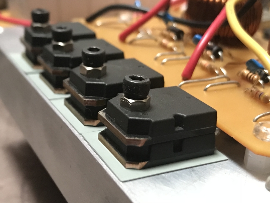
これで、理論上はピーク300[A]に耐えられるブリッジ回路になったはずです。といっても、素子の足の細さだったり配線インダクタンスや素子の個体差などで、実際はそこまで流せないと思います.。とりあえずコレで100[V]以下の入力には耐えて欲しいものです(切実な願い)
にしても、20[V]入力でも大分発熱してヒートシンクが暖かくなるので、素子にもそれほど余裕が無いのかもしれませんので、そのうち強い素子をDigikeyで買おうかなぁとも考えています。とりあえず考えているのはコレ。
連続でも120[A]流せる事になってますが、どうなんでしょう、、、使ってみないと分かりませんね^^;
あとコレも。
コッチはC-E間耐圧が1200Vの物です。安心感を求めるなら良いかもしれませんがやはり高いですね^^;
mini DRSSTC トロイド作るよ
トロイド作った! 以上! それだけ!

mini DRSSTC ブリッジ基板つくるよ
テスラコイルのパワー回路メイン部。主回路、いわゆるブリッジ回路の製作に取り掛かりました。この基板はIGBT4つの簡単なフルブリッジ回路。今回ゲートドライブの方式にGDT (gate drive transformer) を使用する事にしたので、このGDTもブリッジ基板に乗っけてしまいます。
まずはGDTを巻いていきます。GDTを作るうえで重要なのは、使用電圧で飽和しない最適なコアを見つけることです。今回使用したのは、毎度僕が愛用してる、「日米無線のジャンク袋」に大量に入っていたトロイダルコアです。このコア、秋月で売ってるIGBT RJH60F6D 位なら 600 [kHz] ほどでも駆動できたりするのでかなり有能みたい。型も分からないのでB-H特性などは分かりませんので, オシロとファンクションジェネレータを用いてちょうどよさそうな巻き数を決定します。

今回のGDTは1次、2次ともに30回巻きです。この巻き数は、一般的なテスラコイル愛好家からすると多く感じるかもしれませんが、ミニテスラにおいて200[kHz]あたりを越えた高周波駆動となると、ある程度インダクタンスが大きくても安定した波形を得ることが出来ます。IGBTの高速スイッチング特性を生かすにはとにかく高い電圧で誘導させたかったってのもありますけど。

巻いたGDTを早速昔作ったコイル試験機に通してみました。まぁまぁな波形だと思います。ターンオフ時のリンギングは、実際にIGBTにゲート抵抗を介して接続すれば気にならないレベルまで落ちると予想できるのでそのまま放置しました。(コイル試験機の出力電流が足りなくてちょっと波形がばらついてますが^^;)

基板の設計はこんな感じです。設計時間は10分くらいじゃないでしょうか(笑)
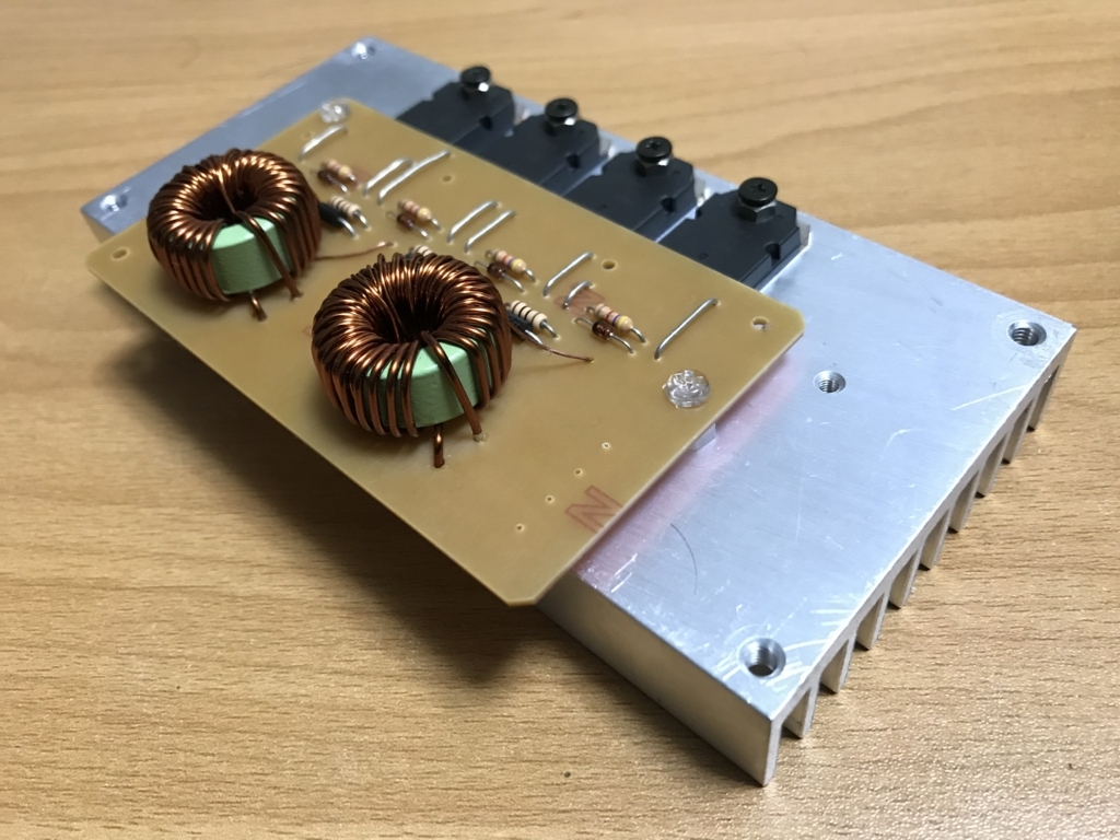
CNCで基板を削りだし、部品を実装したらこんな感じになりました。ヒートシンクは秋葉原のラジオデパートの3階のお店で安売りしてたものです。
GDTドライバ基板もついでに作ってしまいました。この基板はただのハーフブリッジドライバで、ドライバICにはIR2108、FETにはこれまたきょうすけ氏から頂いたTK15J50D を使用しました。

この基板、実物の写真撮るの忘れてしまった…^^;
この段階で、mini DRSSTCの基板が全て完成! パーツ点数を減らした設計にしたのもあって、全体でもかなりコンパクトです。

各基板の結線も済ませてしまいました。

現段階ではそこらへんにおちてた適当なビニル被覆線を使ってますが、最終アセンブル時に銅板での配線に変える予定です。これでも問題なさげではありますが精神的に配線は増強したい次第…。
mini DRSSTC MMC基板つくるよ
ミナサマ方の協力によりコンデンサも調達できたので、早速MMC基板の製作に取り掛かります。今回の設計では、1次回路のインピーダンスを大きくするために適当なコンデンサ容量を決定しました。とりあえず10[nF]前後であれば設計通りの動作をする計算なので、そのあたりの容量になるようにコンデンサを直列接続。今回、きょうすけ氏から頂いた0.068[uF]の豆腐コンデンサを5つ直列にし、大体13[nF]程の容量を達成しました。少し大きいような感じもするけど、それは後々調整できますのでココではとりあえず5つ直列で行きます。
AutoCADでパターンを引き、今回は自宅の中華CNCで切削しました。

この中華CNC、買ったは良いけど精度的にも構造的にもダメダメな代物で、少し改造しております^^; 元はエンドミルがモータ軸と直でカップリングされてたのですが、どう考えても長すぎ… エンドミルが移動するとエンドミルが斜めって進んでいく...(エンドミルは普通に折れました) この問題はベルト駆動に改造して解決です。
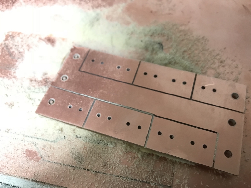
こんな感じになりました。ただコンデンサを直列にするだけなので非常に簡単なパターンです。この基板には瞬間的とはいえバカデカい電流が流れるのでパターンは太めに取ります。

コンデンサを実装してMMC基板は完成です。