How to design Tesla coil (en)
About the design method of the coil part of Tesla coil, since various things were found by our own research (lol) and survey, we introduce it collectively. In addition, the method written in here is "my way".
First of all I will explain the principle appropriately. If you only want to know the procedure, you do not have to read it.
The best coil for Tesla coil
In Tesla coil, it is obvious that maximizing performance can not be obtained by sloppily winding the coil. "The performance" mentioned here is how much the topload voltage can be raised when the secondary circuit completely resonates. Even in the secondary circuit of the same resonance frequency, there are infinitely many combinations of the coil diameter, length, and capacitance of the Topload, but in particular it is about finding combinations that can achieve the spark length. If you make the best coil, you can concentrate on the task of tuning the resonance frequency and you can get the longest spark against the input voltage to the Tesla coil as long as you find the optimum resonance point. Tesla coils look easy if you look at only the structure, but it is quite a deep thing if you examine it in detail. Since there are several matters to determine the voltage of the secondary coil in the Tesla coil, we will explain each in turn.
Structure of Tesla coil
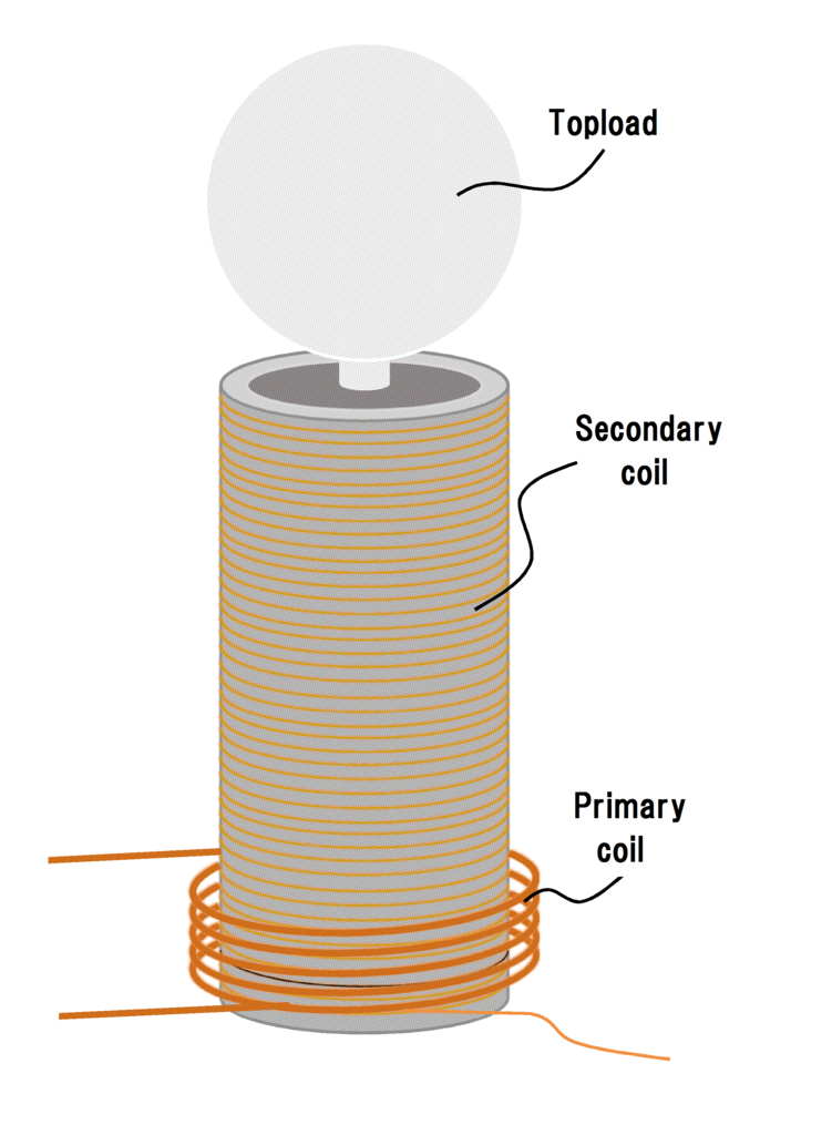
The structure of Tesla coil is as follows.

It has a structure that contains a secondary coil with a lot of thin wire wound in a primary coil wound several times with a wire with relatively good electrical conductivity. In addition, the lower end of the secondary coil (the portion close to the primary coil) is grounded to the ground in good quality, and conversely the capacity ball (Topload) is connected on the upper side. In fact, Topload will function as a spark electrode. The schematic of the Tesla coil focusing only on the structure is shown below.

The structure is very simple like this, but if you write it with a detailed circuit (equivalent circuit) which considered electricity as impedance, magnetic coupling, parasitic capacitance etc. various kinds of basic foundation, it becomes as follows.

It is somewhat complicated like this. In order to wind the best coil, calculating the circuit equations of such an equivalent circuit can calculate optimal quantities (inductance, capacitance, etc.), but it is very complicated and not considering various physical phenomena at all It will not be a perfect result.
Okay, the explanation of the structure of Tesla coil is over with this.
How to extend the spark length of Tesla coil
Since it is making a Tesla coil, it is probably where you want to make the length of the spark as long as possible. Let's think about how to earn the spark length in the Tesla coil. Although it is not a mistake to say that the spark length is determined by the voltage, the state of the spark is a phenomenon largely dependent on the environment. For example, its shape and length greatly vary depending on many physical properties such as atmospheric pressure, temperature, kind of gas, magnetic field, electric field, voltage waveform, etc. However, since it is explained in the case of the standard case, here the environment is assumed to be 1 atm of standard air.
So I think in the future with a simple thinking that if the voltage is raised anyway the spark length will be long. As a method of increasing the voltage of the secondary coil, the following can be considered.
・ Increase the voltage applied to the primary circuit
・ Increase the current of the primary coil
・ Adjust the resonance of the secondary circuit more accurately
・ Increase the Q factor of the primary circuit and the secondary circuit
・ The secondary coil is wound so that the wavelength of the voltage waveform of the secondary circuit becomes appropriate
・ Adjust the coupling coefficient k appropriately
・ Make a structure that does not wastefully sparks
○Increase the voltage applied to the primary circuit
This is understandable given the principle of the transformer. If the voltage of the primary circuit is high, the voltage of the secondary side naturally increases proportionally. However, in reality it will be limited by the capacity of the power supply, the withstand voltage of the capacitor in the case of SGTC, and withstand voltage & permissible current of the semiconductor element in the case of SSTC.

The vicinity of the primary coil of the secondary coil can be seen as a simple air core transformer. Therefore, depending on the number of turns of the secondary coil near the primary coil, the voltage induced to the secondary side changes. The value of this voltage is an important factor for the final output voltage of the secondary circuit.
○Increase the current of the primary coil
DRSSTC was thought to accomplish this. A resonance capacitor is connected also to the primary circuit, and by making it resonate, a large current flows in the primary coil. As a result, the magnetic flux density becomes higher and the voltage induced in the secondary coil also increases.

In the case of only the primary coil, the current flowing through the primary coil is limited, so the current flowing through the primary coil is limited by the reactance component of the coil and the winding resistance. However, if a capacitor is connected in series to the primary coil and this circuit is driven at the resonance frequency, the reactance component in the primary circuit will be equivalent to eliminating the reactance component in the primary circuit, It becomes only winding resistance. Since the primary coil is usually composed of a thick and sturdy wire and the number of turns is not so much, it is likely that the resistance value will be less than 0.5 [Ω], so depending on the drive voltage it will instantaneously be about several thousand [A] Current can flow.
○Adjust the resonance of the secondary circuit more accurately
The more accurately resonating, the smaller the impedance of the secondary circuit becomes, and the voltage between the Topload and the ground becomes maximum.
○Increase the Q factor of the primary circuit and the secondary circuit
The Q factor is a value indicating the quality of the resonance circuit. In the RLC series resonant circuit, the larger the inductance, the smaller the capacitance and resistance, the higher the Q factor. In other words, the Q factor can be increased by "wring the wire as much as possible with as much wire as possible and winding as much as possible." When the Q factor of the primary circuit is high, a larger current flows through the coil during resonance and a higher voltage is induced on the secondary side. Also, if the Q factor of the secondary circuit is high, the voltage across the secondary circuit will be high. In the LC series resonant circuit, a voltage Q times the input voltage appears theoretically at both ends of the capacitor C. (C is Topload in the case of Tesla coil)
○The secondary coil is wound so that the wavelength of the voltage waveform of the secondary circuit becomes appropriate
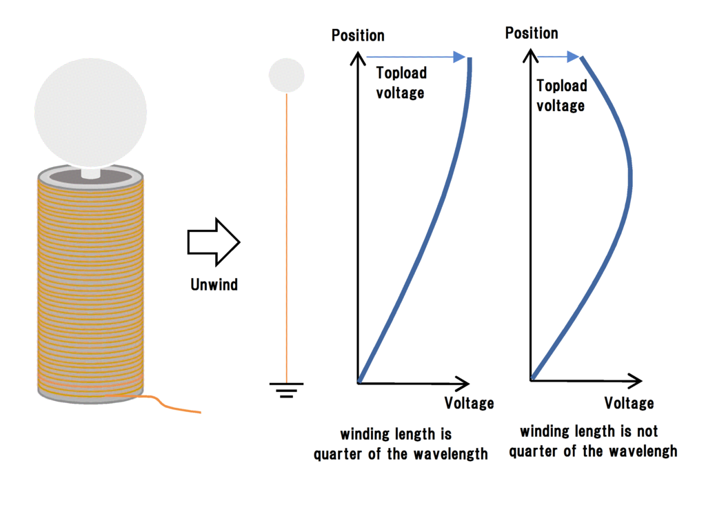
The speed of voltage is said to be nearly light speed in copper wire. Since high frequency alternating current flows in the secondary coil, if the tip of the Topload is adjusted so that it becomes the maximum part of the voltage waveform, the voltage appearing in the Topload part increases. This is the same as the antenna used for radio wave emission etc, and design the secondary coil and the Topload so that the conductor length of the secondary circuit becomes quarter wavelength of the secondary voltage waveform. In the point that the lower part is grounded, the Tesla coil's secondary circuit is like a monopole antenna.

In the case where the secondary coil is unwound as shown in the above figure, in the case where the secondary circuit length determined from the wire length + the conductor length up to the Topload + the earth conductor length is quarter wavelength of the driving frequency and the case where it is not , I think you can see that the ground voltage of the Topload part changes. In other words, it is important to match the wavelength of the resonance frequency with the wire length as much as possible in designing the secondary coil.
○Adjust the coupling coefficient k appropriately
In order for the secondary side to resonate, the coupling between the primary coil and the secondary coil should not be too strong so as to prevent free oscillation of the voltage. Well, most Tesla coils are supposed to be air core coils, so it will be at most as high as k = 0.1 to 0.3. According to my experiment, the coupling coefficient was the best for k = 0.25. The coupling coefficient is a coefficient determined by the coil shape, the distance between two coils, and the magnetic permeability of the environment.
○Make a structure that does not wastefully sparks
Spark occurring in places other than the Topload is completely wasted and losses. To prevent this, you must consider the structure of the coil firmly. For example, take a sufficient distance not to spark between the primary coil and the secondary coil, or make the primary coil flat coil.
How to design the best coil
If coils are designed based on the above matters, it can be said that it is the best coil. However, it is not so easy to design a coil that satisfies all these conditions in a well-balanced manner. Then, let's explain how to actually design the secondary coil.
From the condition shown in "How to extend the spark length of Tesla coil", various relational expressions are obtained from the resonance frequency, the inductance, the propagation speed of the voltage, the capacitance of the wire, the calculation formula of the Q factor, etc., As a result of concretizing relations using data obtained from the results and existing papers, the following formula was derived. Shall I call it "Kamomesan's formula" (lol)

N is the number of turns of the secondary coil. The formula is wonderful. In making a Tesla coil, just by knowing the diameter w of the magnet wire to be used and the capacity C of the topload, the coil that almost cleared the conditions described in "How to extend the spark length of Tesla coil" It is possible to wind it. In addition, wire diameter and topload capacity are values that can be easily set by your preference. Since we only need to wind the secondary coil as many times as required by kamomesan's formula, we only determine the resonance frequency by measurement and create a primary circuit that matches the resonance frequency. In kamomesan's formula, the relationship between the capacitance of the optimum topload and the number of turns can be found, so by filtering the relation as high as possible for the Q factor, the best coil can be designed. The Q factor of the RLC series resonance circuit can be calculated by the following equation.

Here, winding resistance R can be obtained from the following equation from the resistivity of copper and the number of turns.

Nagaoka coefficient A is necessary to calculate inductance L, but since the calculation of Nagaoka coefficient is very complicated, it is calculated by using the approximate expression of the coil diameter length ratio 'a' and the Nagaoka coefficient independently calculated.


The Q factor can be calculated by substituting the calculated winding resistance R, inductance L and the capacitance C of the topload into the expression of the Q factor. By using kamomesan's formulas and Q factor calculation formulas, we can calculate the relationship between the resonance frequency, Q factor, and number of turns when the capacitance of the topload is used as a variable as shown in the graph below.

It is a relationship of various values when wire diameter is 0.3 [mm] when wound on VU 65 (PVC pipe). The frequency of the primary circuit that can actually be fabricated is limited by the response speed of switching semiconductors and others. Here, assuming that the maximum oscillation frequency of the primary circuit that can be manufactured is 500 kHz, the number of turns is about 626 turns, the capacity of the topload is 10 pF, and the Q factor is 894 from the upper graph And you can ask. When winding the secondary coil according to this value, the coil can be made to satisfy the condition shown in "How to extend the spark length of Tesla coil". As you can see from the graph, the higher the frequency that can be oscillated in the primary circuit and the higher the voltage of the primary circuit, the more severe the tuning will be but the larger the Q factor will be, the greater the spark expected You will be able to do.
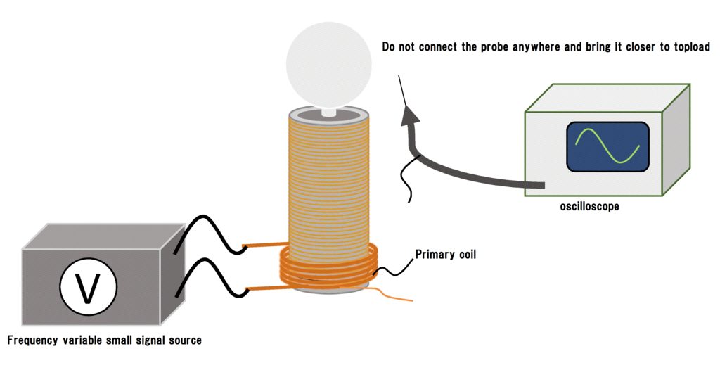
Once the secondary coil can be designed, next is the primary coil. By winding an appropriate primary coil coil at the bottom of the secondary circuit created above and inputting a small signal rectangular wave, measure the resonance frequency of the secondary circuit using an oscilloscope. Set the equipment as shown below and find the frequency (resonance frequency) at which the amplitude of the waveform displayed on the oscilloscope is maximized by adjusting the frequency of a frequency-adjustable small-signal rectangular wave source (it can be a sine wave). The thing to watch out at this time is that it is an error in measurement, so not to bring your hands close to the topload and not to bring the probe closer to the topload. The worst the oscilloscope breaks when the spark strikes the probe :( Because the waveform changes largely at the distance between the topload and the probes should be fixed somewhere.

In the absence of an oscilloscope, there is also a method of estimating the resonance frequency directly by measuring the inductance with the LCR meter, but in this case it is difficult to measure the capacitance of the topload and the resonance frequency can not be obtained successfully. If you do Tesla coil, I think that it is better to own about 1 oscilloscope. Since it will certainly come to be used even in future electronic work :)
After that it is easy to design a primary circuit that resonates at the measured secondary side resonance frequency. In this case,
○ The wire used for the primary coil is as thick as possible and uses a material with good electrical conductivity such as copper.
○ Increase the winding turn of the coil as much as possible.
○ To prevent spark between primary and secondary coils, separate the secondary coils to some extent. How much potential difference can be made between the primary and secondary coils (this is the cause of the spark) depends on the length of the ground wire and the shape of the primary coil, so depending on the size of the Tesla coil It may be better to separate at least 10 mm.
○ Inverse cone shaped coils are not recommended. Electromagnetically there is no advantage to make that shape.
Anyway, if you do not let the primary coil burn and spark between the secondary coils, it will not have any problem.
Final Tesla coil design procedure
By using the led kamomesan's formulas it is easy to design a secondary coil optimal for Tesla coil. The procedure will be roughly as follows.
① Roughly decide the size of the Tesla coil you want to make.
② Determine the diameter of an air core barrel (such as PVC pipe) around which the secondary coil is wound.
③ Worry about the size of the Tesla coil and determine the diameter w of the magnet wire used for the secondary coil. (I will know the ideal wire diameter for the coil diameter in later verification.)
④ Determine the size of the topload and the approximate electrostatic capacity C by using an external site.
⑤ Assign the determined values w and C to kamomesan's fomula to obtain the number of turns N of the secondary coil.

⑥ Purchase the material that can produce the capacity bulb of the determined size and the magnet wire for the secondary coil.
⑦ Wind the secondary coil by the determined number of turns, and make topload as designed.
⑧ Combine the secondary coil and the topload, wind the suitable primary coil, and measure the resonance frequency.
⑨ Make sure not to spark between the secondary coils so as to resonate with the resonance frequency of the measured secondary coil and not to burn, and form a primary circuit.
⑩ Adjust the topload finely until it is convincing.
⑪ Well done !!
I prepared an Excel sheet that can easily calculate the kamomesan's formula, so please use it if you like. ↓
TeslaCoil_calclation_form(en).xlsx - Google ドライブ
Validation of kamomesan's formula
Using the led kamomesan's formula, I'd like to actually set some cases and calculate what is the optimum coil.
○[Question 1] There is Mr. A who can design a primary full bridge circuit with a maximum frequency of 500 [kHz]. Assuming that Mr. A has a pipe of VU 250 and UEW of φ 0.4 [mm], in order to maximize the spark length, Mr. A has to know how many turns of the secondary coil should be wound and how many topload capacity ?
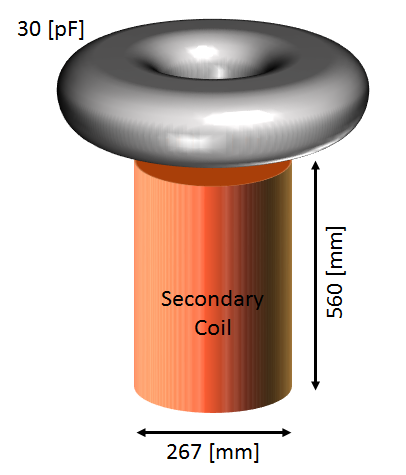
Since UV250 is known to have a diameter of 267 [mm] and a magnet wire diameter of 0.4 [mm], the coil diameter D is 267.4 [mm] and the wire diameter w is 0.4 [mm]. Substitute these values into kamomesan 's formula and further calculate the Q factor to obtain the characteristics shown in the graph below.

From this graph, in order to obtain the longest spark at 500 [kHz] of the primary circuit made by Mr. A, the number of turns of the secondary coil is 1400 [times] and the electrostatic capacity of the topload is determined to be 30 [pF] you will. By the way, the Q factor is 523. Therefore, the secondary coil to be made by Mr. A will be as follows.

Actually, it seems that the sparks is in contact with the bottom due to the short coil, so I think that it will be structurally devised to extend the spark length from here. It is also good to take the topload to a higher position, pack the insulation in the pipe that wound the coil, reduce the grounding resistance, or change the magnet wire to a thicker one if you are stuck, then rewind :)
○ [Question 2] There is a Mr. B who has a secondary coil with VU 65 winding UEW of φ 0.1 [mm] 1500 times. In order to maximize the spark length, Mr. B prepares what a pF toroid is, and ask what [kHz] is the oscillation frequency of the primary circuit.
The diameter of the VU 65 is 76 mm and the diameter of the magnet wire is known as 0.1 mm, so the coil diameter D = 76.1 mm and w = 0.1 mm. By assigning this to kamomesan's formula and calculating the Q factor from the relation obtained by this, the characteristics shown in the graph below are obtained.

From this graph, it is required that the capacitance of the toroid necessary to maximize the sparks is 16 [pF], and the resonance frequency at this time is 202.6 [kHz]. By the way the Q factor is 256.
○ [Question 3] There is Mr. C who can design a primary full bridge circuit with a maximum frequency of 600 [kHz]. Assume that there is a pipe of VU 600 and UEW of φ 0.6 [mm]. In order to maximize the spark length, Mr. C how many times should the secondary coil be wound and what is the capacity of the topload Find what [kHz] the oscillation frequency of the primary circuit should be.
Since UV600 is known to have a diameter of 632 [mm] and a magnet wire diameter of 0.6 [mm], coil diameter D is 632.6 [mm] and wire diameter w is 0.6 [mm]. Substitute these values into kamomesan 's formula and further calculate the Q factor to obtain the characteristics shown in the graph below.

From this graph, in order to obtain the longest spark, the number of turns of the secondary coil is 252 [times], the capacitance of the topload is 8 [pF], and the oscillation frequency of the primary circuit is 252 [kHz] . By the way, the Q factor is 2660. In this coil, you can see from the number of turns and wire diameter that the height is 151 [mm], which is thick and short coil. Since this shape is not suitable for earning the spark length, actually it will be necessary to give up Q factor somewhat and to rewind the wire diameter with a larger thing or to make the toroid bigger. From this, we can see that big toroids and thick windings are required as we get big sparks with big coil.
Actually experiment.
in preparation